Views: 0 Author: Site Editor Publish Time: 2026-11-18 Origin: Site
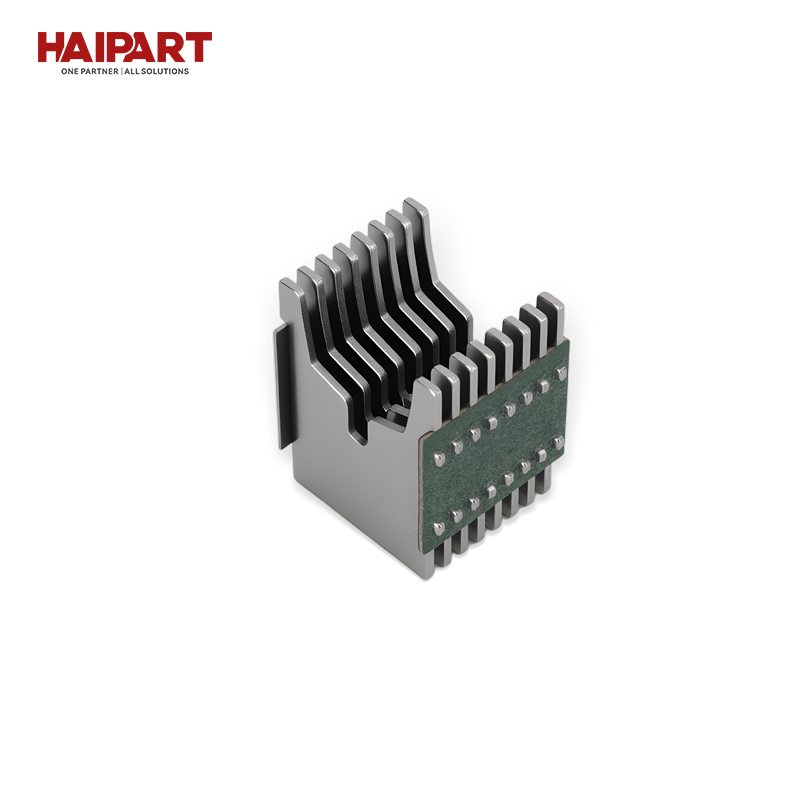
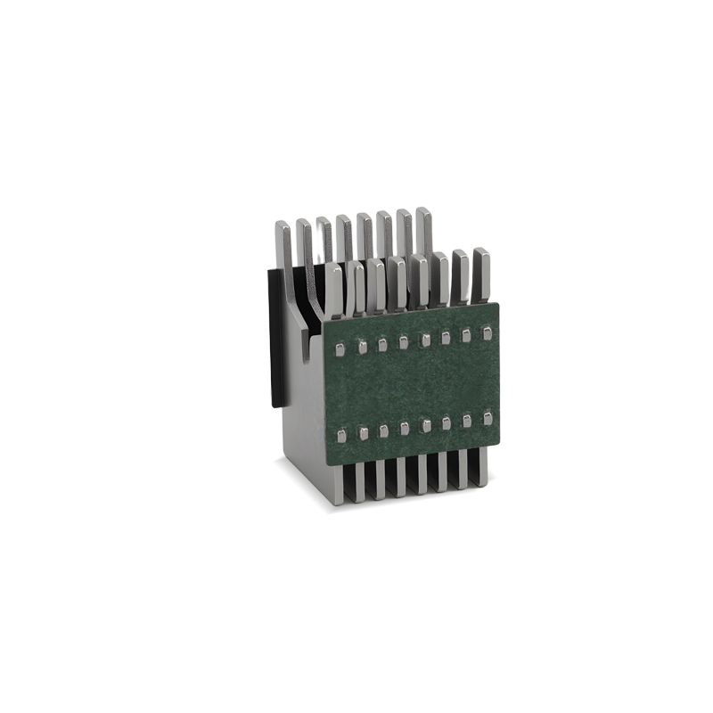
Arc chute plate spacing plays an important role in the arc extinguishing performance of a Miniature Circuit Breaker (MCB). When the breaker contacts separate during a short circuit, an electrical arc forms and generates intense heat. The arc chute uses a series of metal splitter plates to divide, cool, and extinguish the arc before it can cause excessive damage to the breaker. The spacing between these plates affects arc splitting, gas flow, heat dissipation, and dielectric recovery. For MCB manufacturers and electrical equipment buyers, understanding these design factors helps evaluate internal construction, short-circuit performance, and long-term reliability. This guide explains how plate spacing interacts with material selection, chamber geometry, and application requirements in modern MCB designs.
Arc Lengthening and Voltage Multiplication: Optimal plate spacing forces the arc to stretch, lengthen, and divide into multiple smaller arcs, increasing the total arc voltage beyond the system voltage to force extinction.
The Spacing Trade-off: Too narrow spacing restricts gas venting and increases the risk of metallic vapor bridging; too wide spacing fails to effectively split and cool the arc, leading to restrikes.
Application Specificity: Arc chute plate spacing requirements shift dramatically depending on the electrical setup, particularly when comparing standard AC applications to the more demanding requirements of DC circuits.
Material Synergy: Plate spacing must be evaluated alongside plate material (typically ferromagnetic steel) and chamber geometry to accurately assess performance.
Compliance & Endurance: Proper arc chute design is non-negotiable for meeting standard short-circuit testing criteria (e.g., IEC 60898-1, UL 489) and ensuring long-term electrical endurance.
Table of Contents
Arc extinction requires rapidly increasing the electrical resistance of the plasma channel. You must drop the fault current to zero before thermal damage melts the housing or adjacent DIN rail components. When contacts separate under load, current keeps flowing through ionized air. The breaker must turn this highly conductive plasma into an insulator instantly. Success means driving the arc voltage higher than the system's recovery voltage.
The interruption starts by lengthening the plasma channel. Electromagnetic forces from the fault current blow the arc away from the contact zone. These forces push the arc toward the extinguishing chamber. You cannot stretch an arc indefinitely inside an 18mm wide MCB. You have to manipulate it.
When the arc hits a stack of de-ion plates, it strikes the metal edges. It splits into smaller, distinct arcs connected in series. Each arc segment develops a cathode and anode voltage drop. Each plate helps divide the arc into smaller segments connected in series. The voltage drops across these individual arc segments contribute to the total arc voltage. As the arc is divided and lengthened, the increased voltage helps oppose the fault current and supports arc extinction.
The total arc voltage equals the sum of the drops across all individual gaps plus the arc columns. This total voltage must exceed the system recovery voltage. If system voltage stays higher, current flows, sustains the plasma, and destroys the breaker.
Thermal management dictates survival. Plasma arcs exceed 5,000 degrees Celsius. You must absorb and dissipate this heat instantly to stop internal components from melting. De-ion plates act as a massive heat sink. Kinetic and thermal energy transfers from the superheated plasma directly into the metal as the arc enters the plates.
Surface area and thermal mass control this cooling rate. Plates need enough mass to absorb thermal energy without melting. The surface area exposed to the arc determines the heat transfer speed. Rapid cooling drops the gas ionization level. This increases the electrical resistance of the arc path and stops the plasma from sustaining itself during high-kA fault clearing.
The physical gap between de-ion plates controls extinguishing efficiency. This spacing balances electrical resistance, fluid dynamics, and thermal limits. Evaluating this gap shows exactly how a breaker handles severe fault conditions on the job site.
A narrow gap lets engineers pack more plates into the same physical footprint. More plates create more arc divisions. This maximizes cathode and anode voltage drops. The configuration drives total arc voltage up fast. It chokes off fault current in a very short physical distance.
However, tight gaps introduce mechanical and thermal risks. Arc heat causes surrounding air and outgassing materials to expand violently. Tighter spacing restricts exhaust pathways for ionized gases. If gases fail to vent, internal pressure spikes. This pressure ruptures the breaker housing or delays fault clearing. Narrow gaps also increase the chance of molten metallic vapor bridging the plates. Bridging shorts out the gap and ruins dielectric strength.
Widening the gap improves fluid dynamics inside the chamber. Better gas flow vents pressure and ionized exhaust rapidly. This reduces mechanical stress on the breaker housing. Wider spacing lowers the risk of molten metal or conductive soot bridging adjacent plates. You maintain internal insulation after clearing the fault.
The main risk of wide spacing is electrical inefficiency. If gaps are too large, electromagnetic forces fail to drive the arc deep into the plates. The arc bypasses the splitter stack. It runs along the edges instead of splitting. Fewer plates mean a lower total arc voltage. The arc sustains itself longer. It can restrike immediately after the alternating current passes through its zero-crossing. This causes prolonged arcing times and thermal failure.
Current type dictates spacing strictness. Alternating Current (AC) passes through a natural current zero twice per cycle. Around each current zero, the arc may temporarily extinguish, giving the arc chute an opportunity to cool and deionize the arc path. The breaker must then withstand the recovery voltage to prevent the arc from restriking. The chamber gets a fraction of a millisecond to cool gases and prevent a restrike. Direct Current (DC) lacks this natural zero-crossing. A DC arc runs continuously. You must force the current to zero entirely through internal resistance.
DC MCBs require specialized arc extinguishing designs because direct current does not provide the natural current zero found in AC systems. Manufacturers may use magnetic blowout systems, optimized splitter plate arrangements, and dedicated chamber geometries to drive the arc into the extinguishing chamber and increase arc voltage. Plate spacing must be coordinated with magnetic field strength, gas venting capacity, and the breaker's rated DC voltage and short-circuit performance. The final configuration depends on the manufacturer's validated design rather than a universal spacing rule.
Evaluating correct spacing requires analyzing the target short-circuit breaking capacity. A 6kA breaker uses different internal geometry than a 10kA breaker. Higher fault currents generate more plasma and higher pressures. You have to balance adding plates for voltage drop against maintaining gaps for gas exhaust.
Manufacturers calculate the ratio of plate thickness to gap distance. Thicker plates provide thermal mass to absorb heat. They also consume space needed for venting or additional gaps. The optimal configuration depends on application demands.
Spacing Characteristic | Primary Advantage | Primary Risk | Ideal Application Context |
|---|---|---|---|
Narrow Gap (< 1.5mm) | Maximum arc voltage multiplication; high resistance. | Restricted gas venting; high pressure; metal bridging. | Compact DC breakers requiring aggressive voltage drops. |
Optimal Gap (1.5mm - 2.5mm) | Balanced voltage drop and pressure relief. | Requires precise manufacturing tolerances. | Standard high-performance AC MCBs (6kA - 10kA). |
Wide Gap (> 2.5mm) | Excellent gas exhaust; minimal bridging risk. | Insufficient arc splitting; high restrike probability. | Lower kA ratings or larger molded case designs. |
Spacing interacts dynamically with other components to form a complete extinguishing system. To evaluate an arc chute, examine how physical gaps work with materials and surrounding structural geometry.
Splitter plate material influences arc behavior within the gaps. Manufacturers stamp plates from cold-rolled steel or copper-plated steel. Steel provides ferromagnetic properties. Massive fault current generates a strong magnetic field. Steel plates distort this field. They create a magnetic pull that actively draws the arc away from contacts and deep into the chamber.
The material and surface treatment of de-ion plates influence their long-term performance. Bare steel may be susceptible to corrosion under certain environmental conditions, while suitable protective coatings can help improve surface durability. The selection of steel grade and surface treatment should consider magnetic properties, thermal resistance, corrosion exposure, and manufacturing requirements. These factors should be evaluated together with plate spacing and chamber geometry to maintain consistent arc extinguishing performance.
Plate shape matters just as much as the distance between them. Most de-ion plates feature a V-shaped cutout facing the contact zone. This V-notch serves a magnetic function. It concentrates magnetic flux at the center of the plate stack. It acts as a guide track. The concentrated magnetic field pulls plasma directly into the deepest part of the V-notch. The arc splits evenly across all plates instead of escaping down the sides.
Arc runners work with this geometry. These conductive metal strips extend from fixed and moving contacts into the extinguishing chamber. They provide a low-resistance path for the arc root. Rapidly transferring the arc root from silver-alloy contacts to runners prevents contact erosion. It forcefully injects plasma into the precisely spaced plate stack.
Arc chute enclosure design plays an important role in managing the pressure and exhaust gases generated during arc interruption. Different chamber configurations use specific venting paths, internal clearances, and structural features to control gas movement and pressure buildup. Plate spacing must be coordinated with the enclosure geometry and exhaust capacity to maintain effective arc splitting while avoiding excessive internal pressure. The final arrangement depends on the complete arc chute design rather than whether the chamber is fully enclosed or semi-enclosed.
Modern MCBs use ablative polymers like nylon or melamine-based compounds for chamber walls. These polymers ablate when exposed to ultraviolet radiation and plasma heat. They vaporize slightly. Vaporization releases cooling gases like hydrogen and nitrogen directly into the arc path. These gases cool the plasma and increase internal pressure.
Outgassing volume interacts directly with plate spacing. Sudden release of ablative gas builds pressure to compress the arc. This increases voltage drop. If plate spacing is too tight, ablative gases push internal pressure past the mechanical limits of the plastic housing. Engineers balance the polymer outgassing rate with the exhaust capacity dictated by plate gaps.
Understanding internal construction is essential for assessing reliability. You cannot rely on external datasheets. Evaluate how internal geometry supports claimed performance metrics.
Miniature breaker engineering challenges stand out when compared to larger devices. Molded Case Circuit Breakers (MCCBs) and Air Circuit Breakers (ACBs) handle higher currents. They also have larger physical footprints. This allows for wider plate spacing, massive thermal mass, and expansive exhaust chambers. MCBs operate under strict spatial limits. Every millimeter of spacing in an MCB requires optimization. An MCB chamber performs the same physics as an ACB but within a fraction of the volume. Plate gap precision becomes exponentially more critical.
Short-circuit breaking capacity must be evaluated according to the applicable circuit breaker standard. For MCBs covered by IEC 60898-1, the rated short-circuit capacity is expressed as Icn. Circuit breakers covered by IEC 60947-2 use rated short-circuit breaking capacity parameters such as Icu and Ics. These ratings have different definitions and test requirements, so they should not be treated as directly interchangeable. When evaluating an MCB, verify its rated breaking capacity, operating voltage, and applicable test documentation against the requirements of the intended electrical installation.
An undersized extinguishing chamber in a breaker claiming high kA ratings is a red flag. A 10kA rating on a breaker with only a few tightly packed plates indicates a problem. If physical volume and spacing fail to align with the thermal and pressure realities of a 10kA fault, the breaker fails under real-world conditions.
Long-term reliability depends on plate spacing structural integrity. Repeated thermal stress from clearing faults warps thin steel plates. Warped plates ruin meticulously calculated spacing. Gaps close entirely, leading to metal bridging. Gaps widen, leading to restrikes.
Request electrical endurance test data from the manufacturer. Look for oscillograms from repeated short-circuit tests. These charts show exact arc clearing times. If clearing time increases significantly after several operations, it indicates internal thermal degradation and warped plate spacing.
Circuit breaker arc chute designs must comply with the applicable product standards and testing requirements. IEC 60898-1 covers circuit breakers for household and similar installations, while IEC 60947-2 applies to low-voltage circuit breakers within its specified scope. UL 489 covers molded-case circuit breakers, molded-case switches, and related enclosures. These standards evaluate overall breaker safety and performance, including relevant short-circuit interruption requirements. Arc chute plate spacing is therefore assessed as part of the complete breaker design and validated through applicable product testing.
Spacing impacts the breaker's Let-Through Energy (I²t) class. I²t measures total thermal energy allowed through the breaker before the fault clears. Effective arc chute design helps control the arc voltage and interruption time, which can influence the breaker's let-through energy (I²t). Actual I²t performance must be verified through the manufacturer's short-circuit test data under the specified operating conditions. Lower let-through energy means less thermal stress on downstream cables and equipment.
Real-world implementation carries specific failure modes. Addressing these risks ensures the breaker performs reliably on the job site.
Extreme heat vaporizes a small portion of silver-alloy contacts during a severe short circuit. This conductive metallic vapor blasts into the extinguishing chamber alongside the plasma. As gases cool, vapor deposits onto de-ion plate edges and surrounding plastic walls.
This deposition reduces effective plate spacing over time. The metallic coating creates conductive paths that bypass intended gaps. This leads to dielectric failure and restrikes. High-quality designs incorporate insulating baffles or apply non-conductive coatings to chamber walls. This disrupts continuous metal vapor deposition and preserves gap electrical integrity.
Rapid exhaust of ionized gas presents a severe risk outside the breaker. Cooled plasma expelled through exhaust ports remains partially conductive for a brief moment. If the breaker housing fails to manage this exhaust, ionized gas bridges phase-to-phase or phase-to-ground clearances within the electrical panel. This causes a secondary, highly destructive arc flash outside the breaker.
Ensure the breaker housing and exhaust ports safely diffuse and de-ionize expelled gases. Internal plate spacing must slow gas velocity enough to allow cooling. The external housing must feature adequate creepage distances and physical barriers to prevent exhaust from compromising adjacent circuits.
To verify proper clearance and creepage management during panel assembly, follow these field inspection steps:
Measure the physical distance between the MCB exhaust ports and the nearest grounded metal enclosure wall.
Inspect the phase barriers between adjacent breakers to ensure they extend past the exhaust venting zone.
Verify that the panel ventilation system provides adequate airflow to disperse ionized gases rapidly after a fault event.
Check the manufacturer specifications for minimum required clearance distances above and below the breaker terminals.
Request internal teardowns and cross-section analyses from manufacturers to visually verify plate count, thickness, and spacing geometry before procurement.
Demand third-party short-circuit test reports from recognized laboratories like ASTA or KEMA to validate let-through energy (I²t) and arc clearing times.
Review electrical endurance oscillograms to confirm internal plate spacing resists warping and degradation after repeated fault clearing operations.
Specify MCBs with specialized tighter spacing and stronger magnetic blowouts when designing panels for continuous DC applications.
A: Optimized spacing maximizes arc voltage and enhances thermal cooling. By efficiently splitting the arc, the breaker safely interrupts higher fault currents without destroying the housing. Perfectly calibrated spacing enables the breaker to achieve a higher short-circuit rating by balancing rapid voltage drop with safe internal pressure management.
A: Overly tight spacing restricts the venting of superheated, ionized gases. This restriction leads to a dangerous internal pressure buildup that can rupture the breaker housing. Narrow gaps also increase the risk of molten metal vapor bridging the plates, which ruins dielectric strength and prevents successful arc extinction.
A: Yes. DC arcs lack a natural alternating zero-crossing, making them continuous and harder to extinguish. DC breakers require specialized, tighter spacing and stronger magnetic blowouts. This aggressive internal geometry forces a higher arc voltage, ensuring successful current interruption without relying on a natural zero-crossing.
A: Steel provides excellent ferromagnetic properties. When a high fault current flows, it generates a magnetic field. The steel plates distort this field, creating a strong magnetic pull. This pull actively draws the electrical arc away from the contacts, lengthening it, and pulling it deep into the splitter stack.
A: Yes. Repeated fault clearing subjects the plates to extreme thermal stress. This stress erodes or warps the plates, altering the precise spacing. Metallic vapor also coats the components, reducing effective gaps. This degradation eventually causes the breaker to fail to extinguish future arcs safely.
A: The V-notch acts as a magnetic guide track. It concentrates the magnetic flux generated by the fault current, rapidly drawing the arc into the exact center of the plate stack. This geometry ensures the arc splits evenly and efficiently across all plates for maximum cooling and voltage drop.
A: Manufacturers use high-power short-circuit testing laboratories to validate designs. They measure let-through energy (I²t), exact arc clearing time in milliseconds, and post-fault dielectric strength. These rigorous tests ensure the chamber design complies with strict safety standards like IEC 60898-1 and UL 489 under real-world fault conditions.