Views: 0 Author: Site Editor Publish Time: 2026-08-11 Origin: Site
Electrical system reliability depends entirely on component-level integrity. A circuit breaker is only as robust as its weakest internal part. Specifying, sourcing, or assembling these devices without a granular understanding of component quality invites catastrophic failure. Weak parts lead to arc flash hazards, premature wear, and non-compliance with international safety standards. You must evaluate every internal mechanism to ensure operational safety.
This guide provides a technical framework for evaluating Circuit Breaker Components. We detail their structural anatomy, functional mechanics, and required manufacturing tolerances. Understanding these elements ensures long-term operational safety and procurement viability. You will learn how material science dictates lifespan, how arc quenching technology varies by medium, and why manufacturing precision equals reliability.
Material Science Dictates Lifespan: The composition of internal contacts (e.g., silver-tungsten, copper-chromium alloys) directly impacts thermal conductivity, contact resistance, and mechanical endurance during fault clearing.
Arc Quenching Technology Varies by Medium: The design and manufacturing precision of arc chutes, vacuum interrupters, or gas chambers determine a breaker's ability to safely dissipate energy, making it a critical evaluation metric for specific application voltages.
Manufacturing Tolerances Equal Reliability: Micro-deviations in the operating mechanism, spring alignment, or trip unit assembly exponentially increase the risk of nuisance tripping or failure to trip under load.
Compliance is Non-Negotiable: Component sourcing and evaluation must strictly align with verifiable testing standards (UL 489, IEC 60947-2, ANSI/IEEE C37) to mitigate liability and ensure system compatibility.
Table of Contents
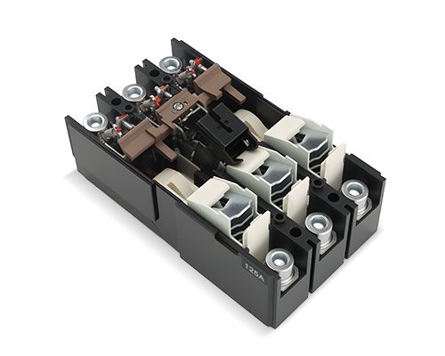
The frame provides structural rigidity and phase-to-phase insulation. It offers environmental protection and internal containment of pressure during fault interruption. The housing holds all internal mechanisms in precise alignment. You must assess dielectric strength and tracking resistance when evaluating frames. Thermal stability dictates how the unit handles extreme fault conditions. Compare glass-reinforced polyester, Sheet Molding Compound (SMC), and Bulk Molding Compound (BMC) against standard thermoset plastics. Evaluate resistance to mechanical shock.
Failure risks include frame cracking under high short-circuit currents. Phase-to-phase flashover can occur if insulation degrades. Environmental exposure to UV, moisture, or corrosive gases accelerates this degradation. A compromised housing threatens the entire electrical panel. When inspecting older installations, look for micro-fractures near the mounting bolts. These stress points often indicate thermal cycling fatigue.
Material Type | Dielectric Strength | Thermal Stability | Common Application |
|---|---|---|---|
Thermoset Plastics | Moderate | Low to Moderate | Residential MCBs |
Sheet Molding Compound (SMC) | High | High | Industrial MCCBs |
Glass-Reinforced Polyester | Very High | Excellent | Heavy-Duty Switchgear |
This mechanical engine opens and closes the contacts. It must achieve sufficient speed to minimize arcing. Velocity profiles dictate the efficiency of the interruption. Evaluate the over-center toggle design efficiency. Spring tension longevity directly affects mechanical life. Mechanical interlock reliability ensures safe operation sequences. Assess independent manual, automatic, and trip-free operation capabilities. Modern magnetic actuator designs offer maintenance-free reliability for specific applications.
Mechanical binding causes severe failures. Spring fatigue reduces contact separation speed. Latch wear or sluggish operation leads to extended fault clearing times. These delays increase the let-through energy, risking severe equipment damage. Field technicians often find hardened grease in older operating mechanisms. This prevents the latch from releasing during a fault.
Isolate the breaker from all power sources before inspection.
Manually charge the closing spring to verify smooth operation.
Trigger the open command and measure the contact parting time.
Inspect the main latching sear for signs of rounding or excessive wear.
Apply approved synthetic lubricants to pivot points, avoiding the contact surfaces.
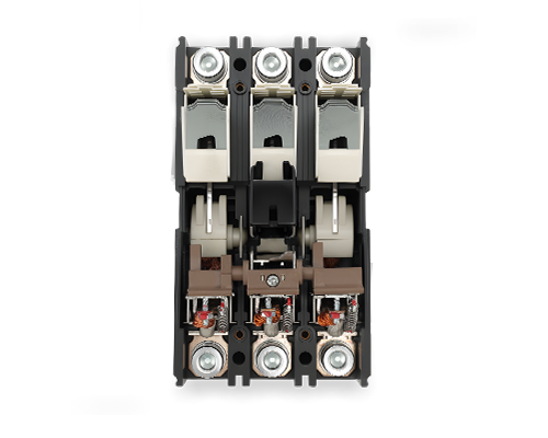
Main contacts carry the continuous load current. Arcing contacts bear the brunt of the electrical arc during separation. Auxiliary contacts signal position status to external control systems. Metallurgical composition is the primary evaluation criterion. Use copper-chromium for vacuum applications. Use silver-tungsten for air and molded case breakers. Evaluate contact pressure springs for consistent force. Inspect surface geometry and plating thickness. Silver or tin plating prevents oxidation.
Contact welding is a catastrophic failure mode. Excessive pitting degrades performance. Oxidation increases contact resistance. Contact bounce during closure causes unnecessary arcing. Increased millivolt drop across the contacts leads to thermal runaway. You should perform routine micro-ohm testing across closed contacts. High readings indicate degrading spring pressure or severe surface pitting.
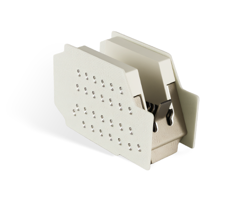
This assembly stretches, cools, and splits the electrical arc. It extinguishes the arc rapidly at current zero. For air breakers, evaluate the number, thickness, and spacing of steel splitter plates. Assess ferromagnetic material quality and exhaust port design. For vacuum breakers, inspect the integrity of the alumina ceramic envelope. Check the stainless steel bellows and internal vapor shields. For gas breakers, measure puffer cylinder volume. Verify PTFE nozzle material quality and gas sealing mechanisms.
Incomplete arc quenching destroys the breaker. Vacuum loss compromises interruption capability. SF6 gas leakage reduces dielectric strength. Internal flashover leads to catastrophic breaker destruction and potential switchgear fires. When evaluating arc chutes, look for heavy carbon tracking or melted splitter plates. These indicate the breaker has cleared a severe fault and requires immediate replacement.
The trip unit senses overcurrent, short-circuit, or ground-fault conditions. It actuates the operating mechanism to open the contacts. For thermal-magnetic units, evaluate bimetallic strip calibration for overload protection. Assess electromagnetic coil responsiveness for instantaneous protection. For solid-state units, verify current transformer accuracy. Evaluate microprocessor reliability and self-diagnostic capabilities. Check the adjustability of LSI/LSIG settings.
Calibration drift causes nuisance tripping. Electronic component failures result from electromagnetic interference. Failure to detect low-level faults leaves the system unprotected. A faulty trip unit renders the breaker useless. Secondary injection testing verifies the trip unit's response curve. You must ensure the unit trips within the manufacturer's specified time bands for long-time, short-time, and instantaneous settings.
Terminals securely connect the breaker to electrical distribution busbars or cables. Draw-out configurations allow for safe isolation and removal. Evaluate the quality of copper bus connectors. Inspect the design of finger clusters on draw-out units. Verify shutter mechanisms operate smoothly. Check the torque ratings of terminal lugs.
Poor contact pressure on line-side clusters causes localized overheating. Deterioration of terminal threads prevents proper torqueing. Racking mechanism jams trap the breaker in the cradle. These issues complicate maintenance and increase thermal risks. Infrared thermography easily identifies loose terminal connections under load. Always use a calibrated torque wrench when terminating cables to the breaker lugs.
Define success criteria based on the specific application. Motor protection requires different characteristics than heavy industrial distribution. Data center selective coordination demands high-precision trip units. Evaluate how specific component upgrades translate to operational outcomes. Electronic trip units offer wave-form capture. Standard thermal-magnetic units do not. Advanced units reduce downtime and enable predictive maintenance. They also lower arc flash energy levels.
Consider the environment when selecting components. High-vibration areas require heavy-duty latching mechanisms. Corrosive environments demand conformal coating on electronic trip unit boards. Matching the component specifications to the physical reality of the installation site prevents premature failures. You cannot rely on standard indoor ratings for outdoor or heavy industrial applications.
Assess the modularity of the components. Determine if trip units, shunt trips, or undervoltage releases can be upgraded in the field. Auxiliary switches should be replaceable without discarding the entire breaker. Evaluate the integration of smart auxiliary components. SCADA systems require reliable data feeds. Building Management Systems rely on accurate breaker status. Industrial IoT protocols like Modbus, Profibus, and Ethernet/IP demand compatible communication modules.
Field-installable accessories save significant time during system upgrades. If a facility adds a remote emergency power off (EPO) system, you need to install shunt trips. Breakers designed with modular accessory pockets allow technicians to snap these components into place without voiding the UL listing. This modularity extends the useful life of the switchgear.
Analyze manufacturer data on maximum switching cycles. Compare mechanical life versus electrical life. Evaluate performance under full load and fault conditions. Determine how component degradation curves impact maintenance schedules. Harsh environments accelerate wear. High ambient temperatures degrade insulation. Vibration loosens mechanical linkages. Coastal salinity causes rapid oxidation. Adjust replacement intervals based on these environmental stressors.
Electrical endurance drops significantly when a breaker clears a short circuit. A breaker rated for 10,000 mechanical operations might only be rated for two or three maximum fault interruptions. You must track fault events. Once a breaker exhausts its electrical endurance, the internal contacts and arc chutes are likely compromised. Replace the unit to maintain system safety.
Manufacturing realities dictate component quality. Stamping, machining, and plating copper conductors require strict tolerances. Powder metallurgy techniques formulate high-performance contact materials. Sintering silver-tungsten creates a durable, arc-resistant matrix. Automated assembly reduces human error. Robotic welding ensures consistent joint strength. Laser-guided tolerance checks verify operating mechanism alignment. This precision prevents mechanical hysteresis and ensures repeatable operation.
The thickness of the silver plating on bus connections directly impacts thermal performance. Thin plating wears off during the racking process of draw-out breakers. This exposes the underlying copper to oxidation. High-quality manufacturers specify exact plating thicknesses and verify them using X-ray fluorescence. This attention to metallurgical detail separates premium components from standard alternatives.
Factory acceptance testing is mandatory. Primary and secondary injection testing verifies trip unit calibration. Dielectric withstand tests confirm insulation integrity. Contact resistance measurements detect poor metallurgical bonds. Advanced diagnostic tests ensure long-term reliability. Helium mass spectrometers detect microscopic leaks in vacuum interrupters and SF6 seals. High-speed X-ray inspection reveals internal welds and casting voids. Manufacturers must validate the calibration curves of all sensing elements.
Field testing mirrors these factory protocols. When commissioning new switchgear, technicians perform insulation resistance testing. They inject current to verify the trip unit responds correctly. They measure the micro-ohm resistance across the closed contacts. These baseline measurements provide a reference point for future maintenance testing. Any significant deviation from the factory test report indicates potential shipping damage or component defects.
Evaluate components against established international standards. IEC 60947-2 governs industrial applications. IEC 60898 covers residential devices. UL 489 applies to molded-case breakers. UL 1066 dictates low-voltage power breaker performance. ANSI/IEEE C37 standards provide comprehensive testing frameworks. Utilizing non-certified components introduces severe legal and safety risks. Self-certified parts lack independent verification. Critical infrastructure requires third-party certified components to ensure safety and compatibility.
Inspectors look for the UL or IEC listing mark on the breaker label. If you modify a breaker with non-certified aftermarket components, you void this listing. The local authority having jurisdiction (AHJ) can reject the installation. Insurance companies may deny claims if a fire originates from unlisted equipment. Always demand verifiable compliance documentation from your component suppliers.
Sourcing aftermarket or third-party replacement parts introduces significant risk. Replacement contacts or trip units must match original specifications exactly. Deviations in metallurgy or spring tension alter the breaker's clearing time. Introducing non-OEM components voids manufacturer warranties. It also invalidates UL and IEC listings. Equipment safety ratings rely on the tested combination of original parts. Mixing components compromises the entire assembly.
We often see facilities try to save money by rebuilding power breakers with aftermarket contacts. The physical dimensions might look identical, but the silver-tungsten ratio is often different. This changes the arc clearing characteristics. During a fault, the aftermarket contacts might weld shut. The cost of replacing destroyed switchgear far exceeds the savings from buying non-OEM parts.
Counterfeit circuit breaker components frequently enter the supply chain. Counterfeit bimetallic strips fail to provide overload protection. Fake electronic chips cause trip unit malfunctions. Implement strict mitigation strategies. Require certificates of conformance for all critical parts. Demand material test reports for metallurgical components. Audit supplier facilities regularly. Utilize only authorized distributors to ensure traceability and authenticity.
Counterfeiters have become highly sophisticated. They replicate manufacturer labels and holographic seals. The only way to guarantee authenticity is through a secure supply chain. Purchase directly from the manufacturer or their authorized channel partners. If a supplier offers a massive discount on hard-to-find components, treat it as a red flag. Verify the serial numbers with the original manufacturer before installation.
Investing in premium components reduces long-term maintenance burdens. Vacuum interrupters and advanced microprocessor trip units cost more upfront. However, they require less frequent manual testing and offer higher endurance. Standard thermal-magnetic breakers are cheaper but demand regular exercising and calibration checks. You must weigh the initial purchase price against the cost of unscheduled downtime and intensive maintenance intervals.
Facilities with high downtime costs, like data centers or continuous manufacturing plants, benefit from premium components. The ability to monitor breaker health remotely via smart trip units saves thousands in labor costs. It also prevents catastrophic failures by alerting operators to degrading contact resistance or abnormal temperature rises before a fault occurs.
Selecting high-quality components is paramount to ensuring overall system safety and operational endurance. As a recognized industry specialist in low-voltage electrical devices and safety solutions, Wenzhou Zhonghui Electric delivers precision-engineered components designed to meet strict international standards and severe operational demands.
Audit your current component specifications against actual facility application requirements to identify mismatched equipment.
Request detailed material data sheets and certificates of conformance from all potential suppliers to verify metallurgical claims.
Establish a strict procurement policy mandating OEM components for all critical infrastructure repairs and upgrades.
Implement incoming quality control checks, including micro-ohm testing, for all replacement parts before installation.
A: The primary components include the frame or housing, the operating mechanism, main and arcing contacts, the arc extinguisher assembly, and the trip unit. Each plays a critical role in sensing faults, separating conductors, and safely extinguishing the resulting electrical arc.
A: Arc chutes consist of a series of metal plates. When the contacts separate, the magnetic field forces the electrical arc into these plates. The plates stretch, split, and cool the arc, increasing its resistance until it extinguishes at the alternating current zero-crossing point.
A: Contact material dictates the breaker's electrical endurance. Alloys like silver-tungsten or copper-chromium resist welding and pitting during high-temperature arcing. Poor materials degrade quickly, increasing contact resistance, which leads to overheating and eventual catastrophic failure.
A: Mechanism failures typically stem from spring fatigue, hardened lubrication, or wear on the latching surfaces. Environmental factors like dust or corrosive gases accelerate this wear. Regular exercise and environmental protection prevent mechanical binding and ensure rapid contact separation.
A: A thermal-magnetic trip unit uses two mechanisms. A bimetallic strip heats up and bends during prolonged overloads, eventually tripping the breaker. An electromagnetic coil responds instantly to massive short-circuit currents, magnetically pulling the latch to open the contacts immediately.
A: Aftermarket parts often deviate from original metallurgical and mechanical specifications. Using them voids manufacturer warranties and invalidates safety listings like UL or IEC. This introduces severe safety risks, including failure to clear faults and potential equipment fires.