

Views: 0 Author: Site Editor Publish Time: 2026-08-11 Origin: Site


The reliability of an electrical protection system is not determined by its external specifications, but by the precision and durability of its internal construction. When a fault occurs, the speed and effectiveness of the interruption depend entirely on the mechanical and metallurgical integrity of the components hidden beneath the plastic housing. Procurement teams, facility managers, and electrical engineers frequently face the challenge of evaluating Miniature Circuit Breakers across varying price points. Without understanding the internal mechanisms, it is difficult to distinguish between a highly reliable breaker and a substandard unit prone to nuisance tripping, contact welding, or catastrophic failure during a short circuit. Evaluating MCB Internal Parts establishes a framework to assess component quality, understand operational trade-offs, and mitigate the risks of deploying inferior electrical protection devices.
Dual Protection Mechanisms: Reliable MCBs rely on a precisely calibrated bimetallic strip for thermal overload protection and a highly responsive magnetic solenoid for instantaneous short-circuit protection.
Arc Chute and Runner Synergy: The speed at which an arc is transferred via arc runners to a high-density arc extinguishing chamber (arc chute) is the primary factor preventing destructive gas buildup and contact wear.
Contact Metallurgy and the Shunt: High-grade silver alloy contacts coupled with a high-conductivity flexible copper braid (shunt) prevent thermal runaway, contact welding, and high internal watt losses.
Ambient Temperature Compensation: Premium MCBs feature a secondary, non-active bimetallic strip to compensate for fluctuating ambient enclosure temperatures, preventing premature thermal tripping.
Housing Integrity Matters: High-quality thermoset plastics are required for the external housing to withstand the extreme thermal and mechanical stresses generated during a fault without deforming or shattering.
Table of Contents
The internal components of an MCB collaborate to interrupt current flow under abnormal conditions without requiring manual replacement. Unlike traditional fuses, which must be discarded after a single fault, MCBs provide resettable protection through a complex interplay of mechanical and electrical systems. You rely on these devices to protect wiring insulation from melting and to prevent electrical fires. The baseline operation hinges on two distinct tripping mechanisms working in tandem to cover the full spectrum of overcurrent faults.
Thermal tripping handles prolonged overcurrents. As current exceeds the rated capacity, it generates heat. This heat causes the internal bimetallic strip to deflect mechanically. The inverse-time characteristic means that higher overcurrents cause faster deflection, eventually triggering the trip mechanism. For example, a slight overload might take several minutes to trip the breaker, allowing for temporary harmless surges like motor startups. A heavier overload will heat the bimetal much faster, forcing a trip in seconds.
Magnetic tripping provides instantaneous response to massive fault currents, such as short circuits. An electromagnetic coil generates a powerful magnetic field within milliseconds during a short circuit. This force actuates an armature, which physically strikes the trip latch, opening the circuit before catastrophic damage occurs. The magnetic trip is a brute-force mechanical override designed to clear faults that are hundreds of times the normal operating current.
The sequential operation chain maps how a fault moves through the system. Understanding this path helps diagnose failures in the field.
Current enters the incoming terminal and passes through the bimetal strip.
The current flows through the flexible copper braid (shunt) to the moving contact.
It crosses the closed contacts to the fixed contact.
The current travels through the magnetic solenoid coil.
Finally, it exits through the outgoing terminal to the load.
When a fault triggers the latch mechanism, the contacts separate rapidly. The resulting electrical arc is then directed into the arc extinguishing system to safely clear the fault.
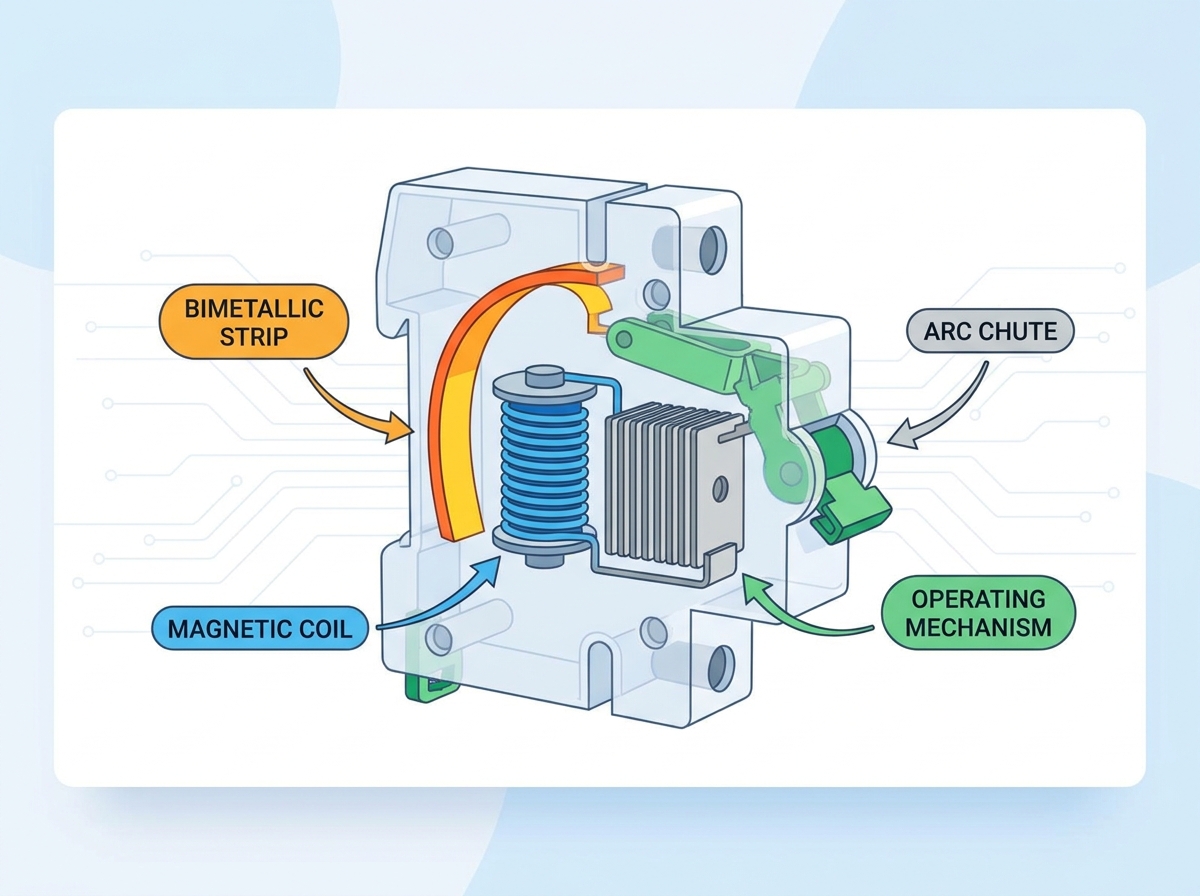
The operating mechanism is the mechanical linkage connecting the external toggle switch to the internal moving contacts. It translates manual operation into internal contact movement and houses the trip latch. This assembly is a marvel of mechanical engineering, utilizing levers and springs to store and release kinetic energy.
A "trip-free" design is a non-negotiable safety requirement. This ensures the breaker will trip internally during a fault even if the external toggle is physically held or locked in the "ON" position. The internal latch releases independently of the external handle state. If an operator tries to force a breaker closed onto an active short circuit, the internal mechanism will still separate the contacts, protecting the operator and the equipment.
The latch holds the spring-loaded contacts in a high-tension closed state. Minimal physical force from either the deflecting bimetal or the striking solenoid armature is required to trip the latch instantly. Once released, the stored spring energy forces the contacts apart. The geometry of the latch determines the sensitivity of the breaker.
Spring tension calibration ensures rapid contact separation. This speed is independent of how fast the operator moves the manual toggle. Rapid separation minimizes the duration of the electrical arc, reducing wear on the contacts and limiting thermal stress on the housing. Weak springs lead to sluggish contact opening, which prolongs arcing and destroys the breaker from the inside out.
The contacts are the physical points where the electrical circuit is completed or broken. They must carry the rated continuous current without excessive heating and withstand the intense heat of arcing during interruption. Contact degradation is the leading cause of breaker failure.
Material science dictates contact performance. Manufacturers use silver-graphite, silver-tungsten, or other silver-nickel alloys. Pure copper is insufficient because it oxidizes rapidly, creating high contact resistance. Copper also has a lower melting point, making it highly susceptible to welding under fault conditions. Silver alloys provide the perfect balance of electrical conductivity and resistance to mechanical wear and arc erosion.
The physical mass, shape, and alignment of the contact tips prevent micro-welding during high-inrush inductive loads. Proper contact profile ensures minimal bounce upon closing and rapid arc transfer upon opening. A wiping action during closure helps clean the contact surfaces of oxides and carbon deposits, maintaining low resistance over thousands of operations.
Contact Material |
Conductivity |
Arc Resistance |
Typical Application |
|---|---|---|---|
Silver-Graphite (AgC) |
Excellent |
Good (Anti-welding) |
Main contacts in standard MCBs |
Silver-Tungsten (AgW) |
Moderate |
Excellent |
High breaking capacity MCBs |
Silver-Nickel (AgNi) |
High |
Moderate |
Low-current control circuits |
Copper (Cu) |
High |
Poor (Welds easily) |
Budget/Substandard MCBs |
The shunt is an ultra-flexible braided copper wire connecting the moving contact arm to the thermal and magnetic trip units. It must carry the full fault current while allowing unrestricted movement of the contact arm. The shunt bridges the static and dynamic parts of the breaker.
This component undergoes significant mechanical stress during hundreds of rapid trip cycles. It must flex instantly without breaking or restricting the speed of the contact separation. If the shunt is too stiff, it slows down the opening mechanism. If it is too thin, it will vaporize during a short circuit.
Quality metrics focus on construction. High-cross-section, multi-strand pure copper braids offer low resistance and high flexibility. Thinner, copper-clad aluminum or alloy alternatives suffer from premature fatigue, increased resistance, and eventual mechanical failure. Broken strands in the shunt increase internal resistance, leading to localized heating and premature thermal tripping.
The bimetallic strip consists of two distinct metals bonded together, each with a different coefficient of thermal expansion, such as brass and invar. As current flows through or around it, resistive heating occurs. The thickness and length of the strip are precisely calculated based on the breaker's ampere rating.
Because the metals expand at different rates, predictable bending occurs under specific thermal loads. This mechanical deflection eventually presses against the trip bar, triggering the latch assembly. The force exerted by the bending strip must be sufficient to overcome the latch friction.
Manufacturers calibrate the strip via adjustment screws during production. Calibration stability is a primary indicator of MCB quality, ensuring the breaker trips precisely according to its published time-current curve over years of service. Poorly calibrated breakers either trip too early, causing nuisance outages, or trip too late, allowing wiring to overheat.
Premium MCBs include an ambient temperature compensator. This secondary, unheated bimetallic strip deflects in opposition to ambient heat. It ensures the breaker trips based on actual circuit overcurrent, preventing nuisance tripping caused by high temperatures within the panelboard. Without this compensator, a breaker in a hot mechanical room might trip at 80% of its rated load.
The magnetic coil is designed with low-resistance copper wire wrapped around a movable iron core, known as the plunger or armature. It carries the load current during normal operation. The coil must be robust enough to handle continuous current without overheating.
During a short circuit, the massive current spike generates a powerful magnetic field. This electromagnetic actuation instantly pulls the armature, causing it to strike the trip lever and force the contacts open in milliseconds. The speed of this operation is what limits the let-through energy of the fault.
The coil turn count and spring resistance dictate the MCB's trip curve. These variations determine the magnetic trip threshold, making specific breakers suitable for different applications.
Type B: Trips at 3 to 5 times rated current. Used for resistive loads like lighting and heating.
Type C: Trips at 5 to 10 times rated current. Used for general commercial loads and small motors.
Type D: Trips at 10 to 20 times rated current. Used for high-inrush inductive loads like transformers and large motors.
When contacts separate under load, a plasma arc generates. This arc reaches temperatures capable of melting internal metals and destroying the breaker if not managed instantly. The arc is essentially lightning contained within a small plastic box.
Arc runners, or arc guides, provide conductive pathways designed to pull the drawing arc away from the opening contacts. They use electromagnetic forces to steer the arc rapidly into the extinguishing chamber. The faster the arc moves off the contacts, the less erosion occurs.
The arc chute consists of a stack of parallel, mutually insulated steel plates, called de-ion plates, encased in insulating material. These plates are the primary defense against arc damage. The spacing and material of these plates are highly engineered.
The arc quenching process involves the arc being magnetically blown into the chute. The de-ion plates divide the main arc into multiple smaller arcs, increasing the total arc voltage, cooling the plasma, and extinguishing it within milliseconds. A higher number of plates generally equates to a higher short-circuit breaking capacity.
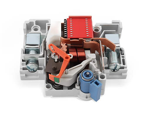
Heavy-duty box or collar terminals secure incoming and outgoing power cables. Mechanical integrity is vital to maintain consistent clamping pressure and prevent high-resistance connections that cause localized heating. Loose connections are a primary cause of panelboard fires.
Material composition varies. High-tensile steel terminals with protective anti-corrosive zinc coatings offer excellent torque retention. Brass or copper-plated terminals may strip more easily under high torque but offer good conductivity. The terminal design must accommodate various wire gauges and types, including stranded and solid copper or aluminum.
IP20 finger-safe terminal shrouds are standard safety engineering features. They prevent accidental contact with live internal conductor entries during installation or maintenance. Deeply recessed terminal screws ensure that a stray screwdriver or finger cannot bridge the gap between phases.
The housing provides structural integrity, aligning internal components precisely. It must also contain the explosive force and hot expanding gases generated during a severe short circuit. The housing is the last line of defense protecting the operator.
Material selection defines durability. Thermoset plastics, like glass-filled polyester, carbonize rather than melt under extreme heat. Cheaper thermoplastics, such as standard nylon, may warp, ignite, or deform under fault conditions, compromising the breaker's structural integrity. A warped housing can jam the internal mechanism, preventing the breaker from tripping.
Molded gas escape ports provide venting channels. They are designed to vent pressurized arc gases safely away from the operator and adjoining breakers, preventing collateral damage within the panel. Proper venting prevents the housing from exploding under the pressure of a high-level short circuit.
Understanding the internal construction allows for accurate quality evaluation. High-quality components ensure reliable operation, while budget alternatives introduce significant risks. You must look beyond the label and understand what is happening inside the device.
Internal Component Evaluation Criteria |
Premium MCB Standard |
Economy / Budget MCB Risk |
|---|---|---|
Arc Chute Plate Density |
11 to 15 de-ion plates (high breaking capacity) |
5 to 7 de-ion plates (limited arc cooling) |
Contact Metallurgy |
Silver-Graphite (AgC) or Silver-Tungsten (AgW) alloys |
Low-grade silver plating over brass or copper |
Bimetal Compensation |
Secondary ambient-temperature compensating strip |
No compensation (prone to summer nuisance trips) |
Internal Connections |
High-grade welded joints and heavy copper braids |
Crimped connections with thin, stiff braided wire |
Housing Material |
Glass-reinforced thermoset plastic (non-flammable) |
Standard thermoplastic (melts/warps under fault) |
Terminal Material |
High-tensile, zinc-plated steel cage clamps |
Soft brass clamps prone to thread stripping |
High-quality internal welding, low-resistance silver contacts, and heavy-gauge braids reduce internal resistance. This lowers power loss across large industrial panelboards, improving overall energy efficiency and reducing heat generation within the enclosure. Lower heat generation extends the lifespan of all components within the panel.
Budget manufacturers reduce costs through material substitution. They use thinner bimetallic strips, fewer arc chute plates, and lower-grade contact alloys. These compromises directly impact the breaker's ability to clear severe faults reliably. A breaker with fewer arc plates will struggle to extinguish a high-current fault, leading to prolonged arcing and potential housing rupture.
Cost-cutting in contact metallurgy leads to the hazard of contact welding. During a short circuit, inferior contacts can melt and fuse together. This prevents the breaker from tripping, allowing the fault current to continue, which often causes localized fires. Welded contacts defeat the entire purpose of the circuit breaker.
Substandard internal parts increase lifecycle costs. They lead to increased maintenance, higher risk of nuisance tripping causing operational downtime, and the potential for catastrophic panel fires requiring complete replacement. The initial savings on a budget breaker are quickly erased by a single failure event.
Standardizing on MCBs with proven internal architectures provides significant value for large facilities. It ensures predictable maintenance cycles and uniform safety standards across all electrical panels. Consistent internal quality means consistent protection.
Counterfeit or low-quality MCBs often weigh significantly less than premium counterparts. This weight discrepancy is due to missing arc chutes, fewer de-ion plates, or reduced copper and silver content. Weighing a sample batch is a quick field test to identify potential counterfeits.
Requesting cutaway samples or performing destructive testing on a sample batch is recommended during large procurement evaluations. This verifies internal construction matches the specified requirements. Opening a breaker reveals the truth about its manufacturing quality.
Verifying compliance with third-party testing certifications is essential. Certifications like IEC/EN 60898, IEC/EN 60947-2, or UL 489 serve as proof of internal component viability and safety compliance. Always check the certification marks and verify them with the issuing agency.
The safety, longevity, and performance of an electrical system are directly dependent on the metallurgical and mechanical quality of the internal components. External specifications only tell part of the story. As a professional manufacturer specializing in high-performance circuit protection and low-voltage electrical devices, Wenzhou Zhonghui Electric is dedicated to delivering reliable quality and engineering excellence across its product line, including the Advanced Molded Case Circuit Breaker - HAIPART. You must prioritize internal build quality to ensure reliable protection.
Request internal cutaway models from manufacturers to physically inspect the arc chute density and contact materials.
Review detailed technical specification sheets to confirm the use of silver alloy contacts and thermoset plastic housings.
Verify that all shortlisted MCBs hold appropriate regional safety certifications and have undergone rigorous third-party testing.
Implement a sample weighing protocol during procurement to quickly identify lightweight, substandard, or counterfeit units.
A: The arc chute divides, cools, and extinguishes the electrical arc generated when the contacts separate under load. It prevents the arc from causing thermal damage or gas explosions within the breaker housing.
A: The bimetallic strip heats up and bends predictably under prolonged overcurrent conditions. This mechanical deflection eventually presses against the trip latch, opening the contacts to protect the circuit from thermal damage.
A: High-quality MCB contacts use silver alloys, such as silver-graphite or silver-tungsten. These materials provide excellent conductivity, resist oxidation, and prevent contact welding during high-temperature fault conditions.
A: The magnetic coil provides instantaneous protection against massive short circuits via electromagnetic force. The bimetallic strip provides delayed protection against sustained, lower-level overcurrents via thermal deflection.
A: Heavier MCBs typically contain higher-quality internal components, such as denser arc chutes with more steel plates, thicker copper braids, and heavier silver alloy contacts, indicating better construction and breaking capacity.
A: No. MCBs are sealed units calibrated at the factory. If an MCB fails or its internal components degrade, the entire unit must be replaced to ensure continued safety and reliable protection.


