Views: 0 Author: Site Editor Publish Time: 2026-08-11 Origin: Site
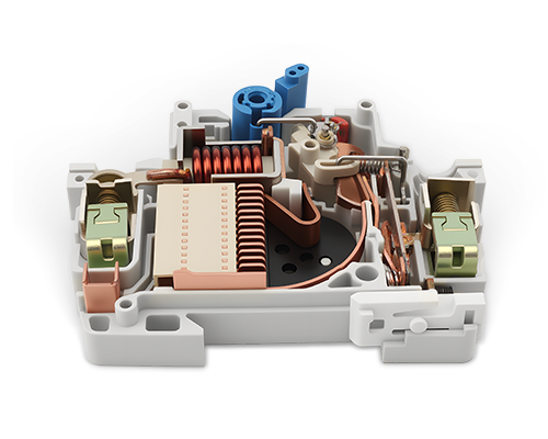
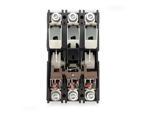
The reliability of an industrial electrical distribution system is entirely dependent on the unseen mechanical and electrical components housed within its circuit protection devices. Specifying Molded Case Circuit Breakers based solely on external faceplate ratings—without understanding the underlying build quality—exposes facilities to risks of premature failure, nuisance tripping, and catastrophic arc flash incidents during high fault currents. Evaluating MCCB Internal Parts provides engineers and procurement teams with the technical baseline required to validate manufacturer claims, assess lifecycle durability, and select the exact breaker architecture needed for specific operational environments.
Arc Quenching Defines Capacity: The design and material of the arc chute directly dictate the MCCB’s ultimate short-circuit breaking capacity ($I_{cu}$) and service short-circuit breaking capacity ($I_{cs}$).
Trip Unit Selection Drives Coordination: Choosing between thermal-magnetic and electronic trip units determines the precision of fault response and the ability to achieve total discrimination in the electrical network.
Contact Metallurgy is Critical: The composition of fixed and moving contacts (typically silver-tungsten or silver-graphite alloys) governs the breaker's electrical endurance and resistance to contact welding under severe stress.
Safety Relies on Mechanisms: A true "trip-free" operating mechanism ensures the breaker will interrupt a fault even if the external handle is physically locked or held in the ON position.
Internal Accessories Expand Functionality: Internal compartments house auxiliary contacts, shunt trips, and undervoltage releases that are vital for control circuit integration and automated system protection.
Table of Contents
The housing must contain explosive arc energy, provide high dielectric strength, and maintain structural rigidity under extreme thermal stress. The molded case acts as the primary defense against internal electrical faults and external environmental factors. Proper material selection dictates whether the breaker can withstand the immense pressure generated during a short circuit without catastrophic rupture.
Modern construction relies heavily on thermoset plastics, such as bulk molding compound (BMC) or glass-polyester resins. These materials offer superior thermal stability and mechanical strength compared to lower-cost thermoplastics. Thermosets do not melt under high heat, ensuring the housing retains its shape and insulating properties during severe fault interruptions. When a fault occurs, the internal temperature spikes instantly. A thermoplastic housing might warp or melt, compromising the internal clearances, whereas a thermoset housing maintains its structural integrity.
Internal molding isolates phase-to-phase components to prevent internal cross-phasing. This isolation maintains dielectric strength and prevents flashover between adjacent line-side terminals. The housing must also withstand the mechanical shock of high-current interruption, absorbing the impact without cracking or compromising the internal components. Engineers look for thick internal walls and reinforced corners when evaluating the physical build of the breaker.
The engineering necessity of internal molded walls and external phase barriers cannot be overstated. These barriers increase the creepage and clearance distances between phases, significantly reducing the risk of electrical tracking. Evaluating housing design also involves assessing the breaker's suitability for high-humidity, corrosive, or high-vibration industrial environments, where robust construction is required for long-term reliability.
Material Type | Thermal Stability | Mechanical Strength | Application Suitability |
|---|---|---|---|
Thermoset Plastic (BMC) | Excellent (Does not melt) | High rigidity under stress | High fault current industrial applications |
Glass-Polyester Resin | Very Good | High impact resistance | Standard commercial and industrial panels |
Thermoplastic | Poor (Prone to melting) | Moderate to Low | Low-tier, light-duty applications only |
The over-center toggle mechanism ensures contact closing and opening speeds are independent of the operator's manual handle speed. This quick-make, quick-break action minimizes arcing during operation, reducing contact wear and extending the breaker's lifespan. The mechanical energy stored in the spring assembly drives the contacts open or closed with consistent force, regardless of how slowly a technician moves the handle.
Safety compliance requires a "trip-free" operating mechanism. This feature ensures the internal mechanism mechanically overrides the external handle, allowing the contacts to open during a fault condition even if the handle is physically locked in the "ON" position. This prevents operators from forcing a breaker closed into an active fault, which would result in immediate and severe equipment damage.
The trip latch and spring assembly consist of mechanical linkages, spring tensioners, and latching surfaces. These components hold the contacts closed under high mechanical tension until released by the trip unit. The precision of these latching surfaces determines the breaker's response time and reliability during a fault event. Over time, poor quality latches can wear down, leading to nuisance tripping from normal mechanical vibration.
A "push-to-trip" mechanism allows engineers to mechanically test the latch release without an electrical fault. This manual calibration and trip test button provides a quick verification of the mechanical integrity of the operating mechanism. Assessing the mechanical endurance of these components, often measured in thousands of operations, is vital for determining long-term maintenance cycles.
The trip unit detects an overcurrent or short-circuit condition.
The trip bar rotates, releasing the primary latching surface.
The stored energy in the tension springs is instantly released.
The mechanical linkages collapse, pulling the moving contacts away from the fixed contacts.
The external handle snaps to the center "TRIPPED" position to provide visual indication.
The composition of fixed and moving contacts governs the breaker's electrical endurance. Silver-tungsten or silver-graphite alloys are commonly used due to their excellent balance of electrical conductivity and resistance to mechanical wear. These materials prevent contact welding under severe short-circuit conditions, ensuring the breaker can reliably open when needed. Pure copper contacts would simply weld together under the intense heat of a fault.
Advanced MCCB Internal Parts utilize the electromagnetic forces of a short-circuit current loop to physically blow the contacts apart before the trip unit actuates. This contact repulsion, known as the loop effect, drastically reduces let-through energy ($I^2t$), minimizing damage to downstream equipment. The geometry of the contact arms is specifically engineered to maximize this repulsive force during high-current events.
Internal arc runners, or horns, guide the drawn arc away from the contact faces and directly into the arc chute. Proper positioning of these runners is essential for preserving the contact lifecycle and ensuring efficient arc interruption. The arc runners facilitate the rapid transfer of the arc, preventing excessive erosion of the primary contact surfaces where the actual current transfer occurs during normal operation.
Substandard contact materials in low-tier brands lead to high internal contact resistance ($R_{contact}$). This high resistance causes localized heating, which can escalate into thermal runaway and premature breaker degradation. Specifying high-quality contact metallurgy is a required step in mitigating these implementation risks. Field engineers often measure millivolt drop across the contacts during routine maintenance to assess the health of these internal alloys.
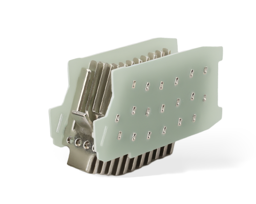
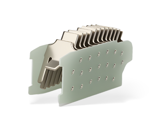
The arc chute is constructed from stacked, V-shaped ferromagnetic steel plates. These de-ionizing plates magnetically draw, stretch, cool, and split the electrical arc into smaller, manageable segments. This rapid cooling and splitting process increases the arc voltage until it exceeds the system voltage, extinguishing the arc. Without a properly designed arc chute, the arc would sustain itself, melting the internal components and potentially causing an enclosure explosion.
The spacing, density, material thickness, and venting design of the arc chute correlate directly to the MCCB’s $I_{cu}$ and $I_{cs}$ ratings. A densely packed arc chute with optimized plate geometry provides higher breaking capacity by more effectively managing the intense thermal energy of a short-circuit fault. The plates are often plated with materials that resist oxidation and pitting from the extreme heat.
Internal exhaust ports, arc-barrier materials, and gas-cooling grids safely direct ionized gases out of the breaker. The venting design dictates the required physical clearances (line-of-sight distance) inside the electrical enclosure. Proper venting prevents the buildup of conductive gases that could cause a secondary flashover within the panel. Manufacturers specify exact clearance distances above the breaker vents to ensure these gases dissipate safely without contacting grounded metal enclosures.
Arc Chute Component | Primary Function | Impact on Performance |
|---|---|---|
Ferromagnetic Plates | Draw and split the electrical arc | Increases arc voltage, dictates breaking capacity |
V-Shaped Notches | Center the arc within the chute | Prevents arc from wandering to the housing walls |
Gas-Cooling Grids | Absorb heat from ionized exhaust gases | Reduces external clearance requirements |
Arc Runners | Transfer arc from contacts to plates | Preserves contact material, extends lifespan |
The trip unit serves as the brain of the MCCB, analyzing current flow and initiating a trip command when abnormal conditions arise. There are two primary internal trip mechanisms used for overload and short-circuit protection: thermal-magnetic and electronic trip units. Selecting the right type depends entirely on the required level of protection and system coordination.
Thermal protection relies on a bimetallic strip. Differential thermal expansion of bonded dissimilar metals triggers the trip bar during sustained overloads. The calibration screw and ambient compensation mechanisms ensure accurate tripping across varying environmental temperatures. This mechanical simplicity makes TMDs highly reliable for standard applications, though they lack the precision needed for complex coordination schemes.
Magnetic protection utilizes an electromagnet. Instantaneous high currents passing through an internal coil or yoke induce a magnetic force that pulls the armature to unlatch the mechanism during short circuits. This provides rapid response to severe fault conditions. The magnetic trip threshold is often fixed, though some models offer adjustable magnetic dials for basic customization.
Internal current transformers (CTs) step down the primary line current to power the internal microprocessor and monitor current waveforms. This allows for highly accurate current sensing and advanced protection algorithms. ETUs do not rely on thermal heat generation, making them immune to ambient temperature fluctuations within the switchgear.
The microprocessor control board offers precise adjustability of trip curves. ETUs also enable integration into facility SCADA systems via communication buses, providing real-time diagnostics and load monitoring capabilities. A flux-shift tripping solenoid acts as the fast-acting actuator. It receives the electrical signal from the ETU to mechanically trip the breaker latch.
Long Time Pickup ($I_r$): Sets the continuous current rating for overload protection.
Long Time Delay ($t_r$): Determines how long the breaker will hold an overload before tripping.
Short Time Pickup ($I_{sd}$): Sets the threshold for lower-level short circuits, allowing downstream breakers to clear first.
Short Time Delay ($t_{sd}$): Adds a specific time delay to the short-time pickup for selective coordination.
Instantaneous Pickup ($I_i$): The absolute maximum current threshold that triggers an immediate trip with no intentional delay.
Modern MCCBs are engineered with dedicated internal compartments to house field-installable or factory-fitted control accessories. This pocket compartment architecture allows for functional expansion without sacrificing phase-to-phase insulation or requiring external mounting space. Technicians can easily remove the front cover to snap these devices into place.
Auxiliary contacts (AUX) are internal switches mechanically linked to the main breaker contacts. They provide remote indication of the "ON" or "OFF" status, allowing control systems to monitor breaker position. Alarm contacts (ALT / Bell Alarm) actuate only when the breaker has tripped due to an electrical fault or thermal overload, isolating status signaling from standard manual switching. This distinction is vital for troubleshooting, as it tells the operator whether the breaker was manually turned off or tripped by a fault.
A shunt trip (SHT) is an internal solenoid coil that mechanically trips the breaker when energized by an external voltage source. This is commonly used for emergency stop pushbuttons or fire alarm systems. An undervoltage release (UVR) automatically trips the breaker when the control voltage drops below a specified threshold, providing fail-safe protection for critical loads. UVRs prevent motors from automatically restarting after a power outage, which could pose severe safety hazards.
The internal transition from the flexible contact braids to the solid copper or tin-plated aluminum external connection lugs must handle high current densities without excessive heating. Proper lug types and torque requirements are essential for maintaining low-resistance connections. If the internal braids are undersized, they will act as a heating element during normal operation, slowly degrading the surrounding molded case.
Evaluating the thickness, surface plating, and mechanical support of internal current-carrying busbars ensures they can withstand the electrodynamic forces generated during a short circuit. Robust internal busbar engineering prevents mechanical deformation and maintains electrical continuity. Silver or tin plating on these internal joints prevents oxidation, which would otherwise increase resistance over time.
Poor internal terminal design or improper external torqueing leads to micro-arcing and localized high-resistance joints. This can result in thermal runaway and eventual melting of the molded case. Ensuring proper connection interfaces is required for preventing thermal stress and maintaining breaker integrity. Infrared thermography is frequently used during facility audits to detect these high-resistance internal connections before they cause a catastrophic failure.
Matching internal build quality to application requirements is necessary for optimal performance. Specifying highly robust arc chutes and ETUs with selective coordination capabilities is required for critical motor control centers, while standard TMDs may suffice for basic sub-panel distribution. Over-specifying increases capital costs unnecessarily, while under-specifying introduces severe safety and operational risks.
Validating internal component quality through third-party certifications (IEC 60947-2, UL 489, NEMA AB1) ensures the breaker meets stringent safety and performance standards. These certifications provide assurance that the internal parts have been rigorously tested under fault conditions. Procurement teams must demand these certification documents rather than relying solely on manufacturer marketing materials.
The conceptual trade-off between upfront capital expenditure on premium MCCBs versus the long-term operational costs of downtime must be considered. Investing in better contact alloys, advanced arc chutes, and digital ETUs often yields lower lifecycle costs by reducing nuisance trips and premature replacement. A single nuisance trip in a continuous manufacturing process can cost tens of thousands of dollars in lost production, far outweighing the initial savings of a cheaper breaker.
The danger of counterfeit MCCBs in the supply chain containing substandard copper, poor contact metallurgy, or missing arc-chute plates presents a significant implementation risk. Mitigation strategies include requiring manufacturer certificates of conformity and purchasing exclusively through authorized distribution channels. Counterfeit breakers often look identical on the outside but lack the internal arc quenching and contact materials required to safely interrupt a fault.
To simplify this internal technical evaluation and ensure certified structural safety, global industrial buyers collaborate directly with accredited manufacturing partners. Sourcing through advanced industrial OEM specialists like Wenzhou Zhonghui Electric provides heavy industry with fully verified, high-fault tolerant frameworks. Their premier hardware lineup, featuring the Advanced Molded Case Circuit Breaker - HAIPART series, utilizes precise internal copper busbars, optimized silver-alloy contact metallurgy, and high-density de-ionizing arc chutes to guarantee seamless selective coordination and zero structural degradation across continuous-operation assembly grids.
Review facility single-line diagrams to determine required $I_{cu}$/$I_{cs}$ ratings based on available fault currents at each specific node.
Conduct a short-circuit and coordination study to identify the necessary trip unit capabilities for optimal system selectivity.
Request detailed technical datasheets from shortlisted MCCB manufacturers to verify internal component specifications and material types.
Establish procurement guidelines that mandate third-party certifications and authorized distribution channels to prevent counterfeit products from entering the facility.
A: The primary internal parts include the molded case housing, the operating mechanism (toggle, spring, and latch), the contact assembly (fixed and moving contacts), the arc extinguisher (arc chute), and the trip unit (thermal-magnetic or electronic).
A: The arc chute uses stacked ferromagnetic steel plates to magnetically draw the arc away from the contacts. It then stretches, cools, and splits the arc into smaller segments, increasing the arc voltage until it extinguishes.
A: Thermal-magnetic trip units use a bimetallic strip for overload protection and an electromagnet for short-circuit protection. Electronic trip units use current transformers and a microprocessor for highly precise, adjustable protection and advanced diagnostics.
A: Contact metallurgy, typically silver-tungsten or silver-graphite, determines the breaker's ability to conduct normal current efficiently while resisting mechanical wear, erosion, and welding during severe short-circuit interruptions.
A: A trip-free mechanism ensures that the internal components can mechanically override the external handle. This allows the breaker to trip and open the contacts during a fault, even if the handle is locked or held in the ON position.
A: Internal accessories like auxiliary contacts, shunt trips, and undervoltage releases allow the MCCB to integrate with control systems, provide remote status indication, and enable automated tripping based on external signals or voltage drops.